
Technical support for this article: R&D Department—Liu Chen
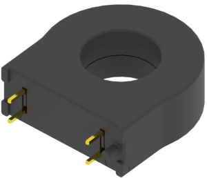
What Is a Current Transformer?
A current transformer consists of a closed magnetic core and windings. In professional applications, current transformers are further divided into phase-sequence current transformers and zero-phase-sequence current transformers.
CT: Abbreviation of the English term phase-sequence current transformer; Chinese name: 相序电流传感器
ZCT: Abbreviation of the English term zero-phase-sequence current transformer; Chinese name: 零序电流互感器
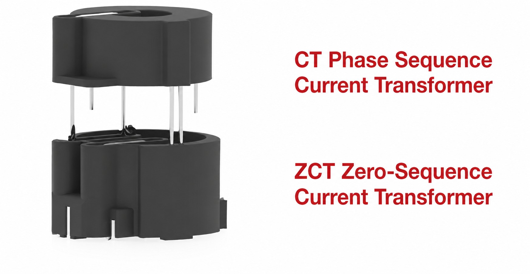
A common question is: phase-sequence current transformers and zero-phase-sequence current transformers are both called current transformers, and both consist of a closed magnetic core and windings. What, then, are the differences between them? The following sections distinguish phase-sequence current transformers from zero-phase-sequence current transformers in several respects.
1. Current Detection
A phase-sequence current transformer is primarily used to detect the phase sequence and RMS value of three-phase AC power, while a zero-phase-sequence current transformer is primarily used to detect imbalance or zero-sequence current in the line and neutral conductors. Phase-sequence currents are generally measured at the ampere level, while zero-sequence currents are generally measured at the milliampere level.
2. Operating Principle
Phase-sequence current transformers and zero-phase-sequence current transformers operate on the same principle. Both use electromagnetic induction to convert primary-side current into secondary-side current or voltage for measurement. The difference is that a zero-phase-sequence current transformer must detect milliampere-level current and therefore requires a core with higher magnetic permeability.
3. Installation Location
A phase-sequence current transformer is typically installed on equipment where phase sequence and current must be detected, such as motors and transformers. A zero-phase-sequence current transformer is typically installed around the line and neutral conductors in a power system to monitor the zero-sequence current of the entire system.
4. Application Scenarios
Phase-sequence current transformers are widely used where phase sequence and current must be detected, including motor control and power system monitoring. Zero-phase-sequence current transformers are primarily used for fault detection and protection on line and neutral conductors.
In summary, the two types differ significantly in operating principle, detected current, installation location, and application scenario. The points above provide a basic understanding of phase-sequence and zero-phase-sequence current transformers. These four points show that phase-sequence current transformers are used primarily for current detection, while zero-phase-sequence current transformers are used primarily for residual current detection.
|
|
Current detection and residual current detection differ in the following respects.
PART.1 Detection Purpose
01 - Current Detection
The primary purpose is to monitor and control current in a circuit, ensuring that it remains within the specified range for normal system operation. Current detection is also used for fault diagnosis and preventive maintenance, such as overcurrent protection and electrical fire prevention.。
02 - Residual Current Detection
The primary purpose is to detect residual current in a circuit—that is, the difference between the currents in the line and neutral conductors when an earth fault occurs (meaning that the vector sum of the currents is not zero). Residual current detection is used primarily to detect and isolate earth faults, preventing incidents such as electrical fires and equipment damage.
PART.2 Detection Principle
01 - Current Detection
Current is measured indirectly by measuring the magnetic field of a conductor or the conductor's temperature. The magnetic-field method uses Ampère's circuital law to measure the magnetic field around the conductor and calculate the current magnitude. The temperature method uses the thermal effect to measure the conductor temperature and calculate the current magnitude.
02 - Residual Current Detection
Residual current is detected by measuring the difference between the phase currents and neutral current (that is, their vector sum). Under normal conditions, the difference between the three-phase currents and neutral current is zero, meaning the residual current is zero. When an earth fault occurs, the residual current is nonzero, and the fault location and type can be determined by measuring its magnitude and direction.
PART.3 Detection Method
01 - Current Detection
Different detection methods may be used depending on the application scenario and requirements. Common methods include air-core devices (Rogowski coils), magnetic-ring devices (electromagnetic induction and fluxgate types), Hall-element devices, and magnetoresistive devices. Among these methods, fluxgate detection offers high accuracy and a wide measurement range and is currently the most widely used method for high-accuracy current detection.
02 - Residual Current Detection
A zero-phase-sequence current transformer is commonly used. The three phase conductors and neutral conductor pass through the same core winding, and residual current is detected by measuring the difference between their currents (that is, their vector sum).
PART.4 Application Scenarios
01 - Current Detection
Current detection is widely used in industrial sectors, household appliances, and other fields to monitor and control circuit current and ensure the normal operation of equipment and systems. Examples include motor overload protection and electrical fire prevention.
02 - Residual Current Detection
Residual current detection is widely used in low-voltage distribution systems to detect and isolate earth faults. Examples include earth-fault protection in residential distribution systems, industrial plants, and commercial buildings.
|
|
Product Features
> Type B onboard residual current protection module designed for EV chargers and compatible with Type A+6
> all-in-one highly integrated digital residual current trip indication
> Integrated current measurement coil (CT)
Standard Compatibility
> Meets the residual current trip characteristic requirements for Mode 2 charging under GB/T 41589 (IEC 62752)
> Meets the RDC-PD residual current trip characteristic requirements for Mode 3 charging under GB/T 40820 (IEC 62955)
> Meets the basic residual current trip characteristic requirements under GB/T 22794 (IEC 62423) and supports DC 6mA test requirements
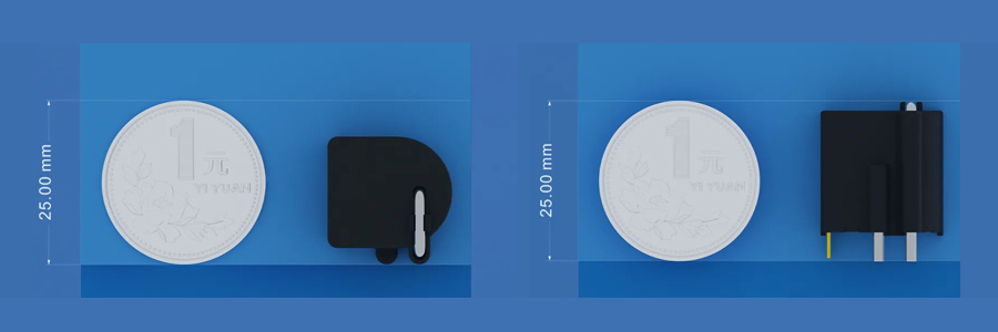
Size Comparison (1-yuan coin)
|
|
In power system protection and monitoring, the main circuit and current transformer are important components for current measurement and protection. Accurate identification of their corresponding-polarity terminals helps ensure accurate current measurement and is therefore important to the safe and stable operation of power systems. The following sections examine methods for identifying the corresponding-polarity terminals of the main circuit and current transformer and analyze common issues in practical applications.
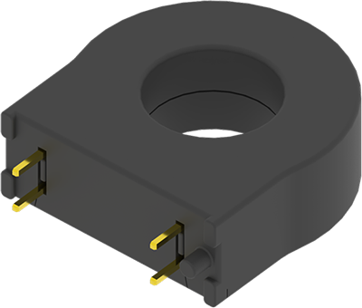
Definition of Corresponding-Polarity Terminals
For two coils, L1 and L2, wound on the same magnetic circuit, when currents of the same polarity (connected to the positive terminal of the power supply) enter terminals 1 and 4, the magnetic flux generated by the two coils has the same direction (Figure 1, both pointing left). If, when the magnetic flux changes, the induced electromotive forces at terminal 1 of one winding and terminal 4 of the other have the same polarity (Figure 2, positive electromotive force), terminal 1 of coil L1 and terminal 4 of coil L2 are corresponding-polarity terminals. The other two terminals, 2 and 3, are also corresponding-polarity terminals, while 1 and 3 and 2 and 4 are opposite-polarity terminal pairs. The figures also show that the coil winding direction determines corresponding- and opposite-polarity terminals. If coil L2 is wound in the same direction as L1, the result is the opposite of the preceding case.
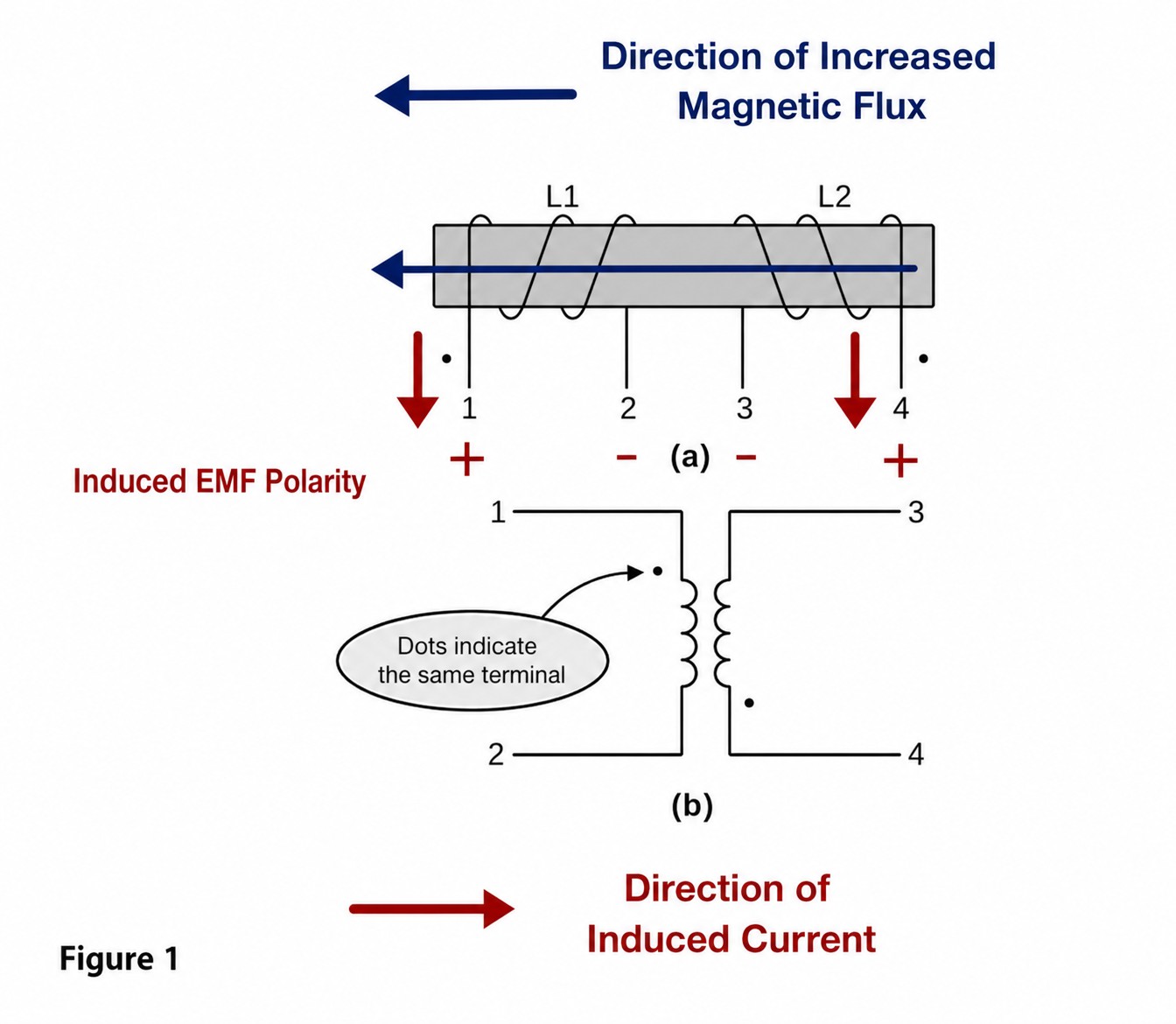
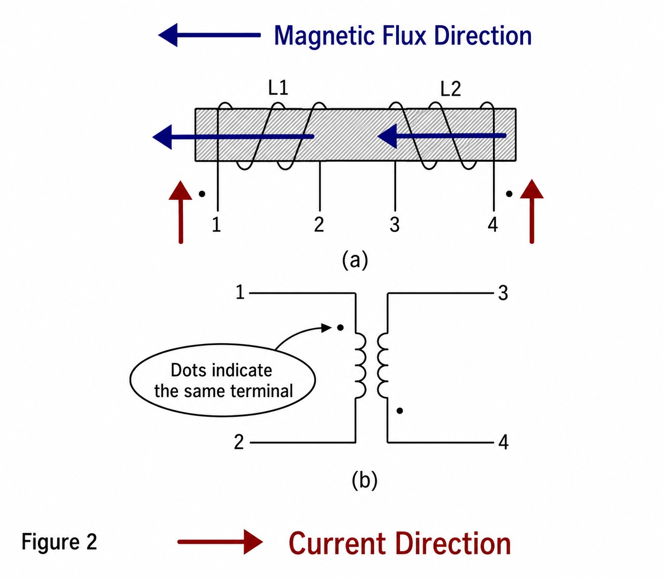
As illustrated in Figures 1 and 2, corresponding-polarity terminals can be readily identified from the winding direction by applying the right-hand screw rule. If the winding direction cannot be seen, measurements must be used. Several methods are described below.
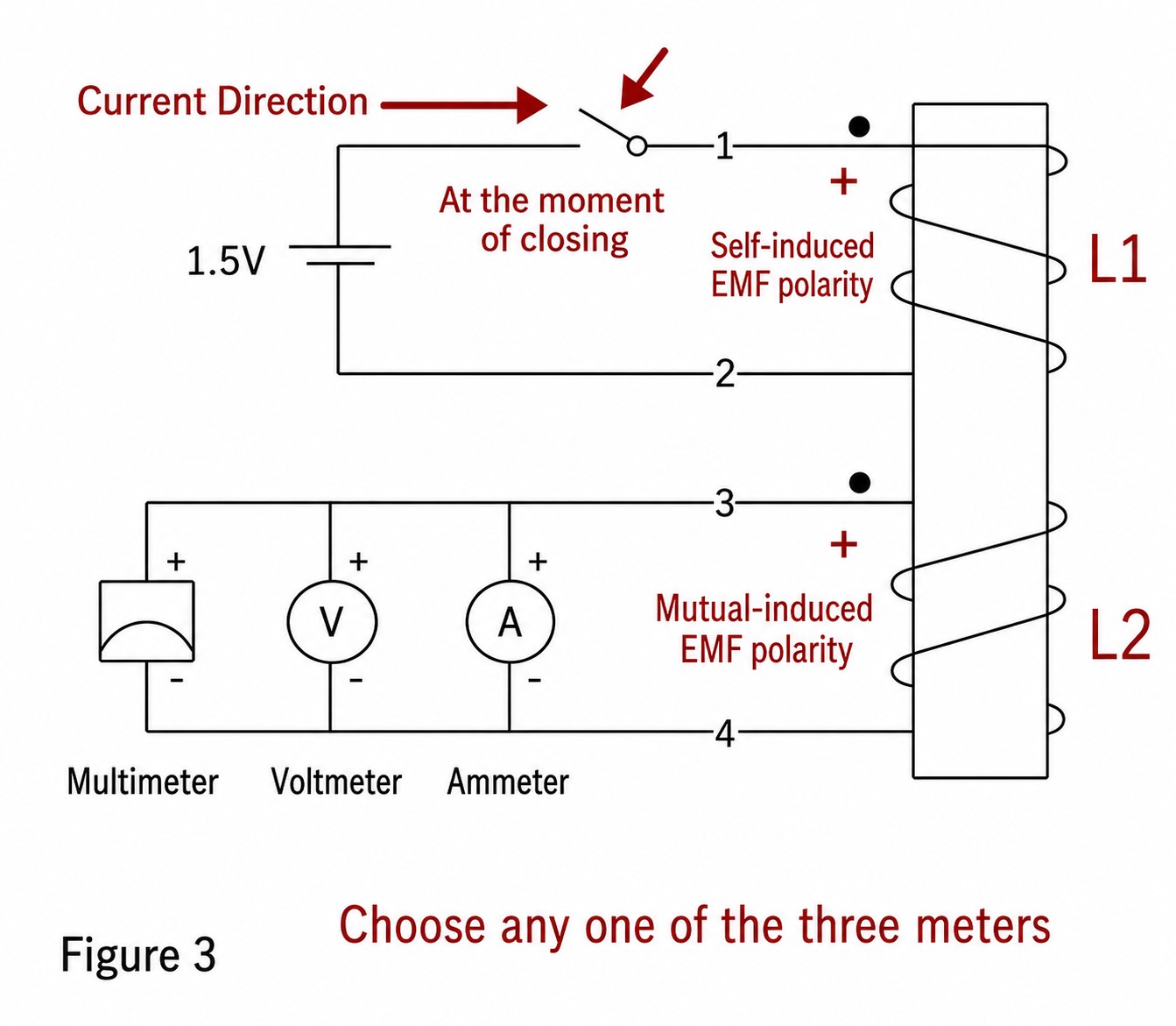
01 Dry Cell and Multimeter Method (or Low-Range Voltmeter, Microammeter, or Ammeter)
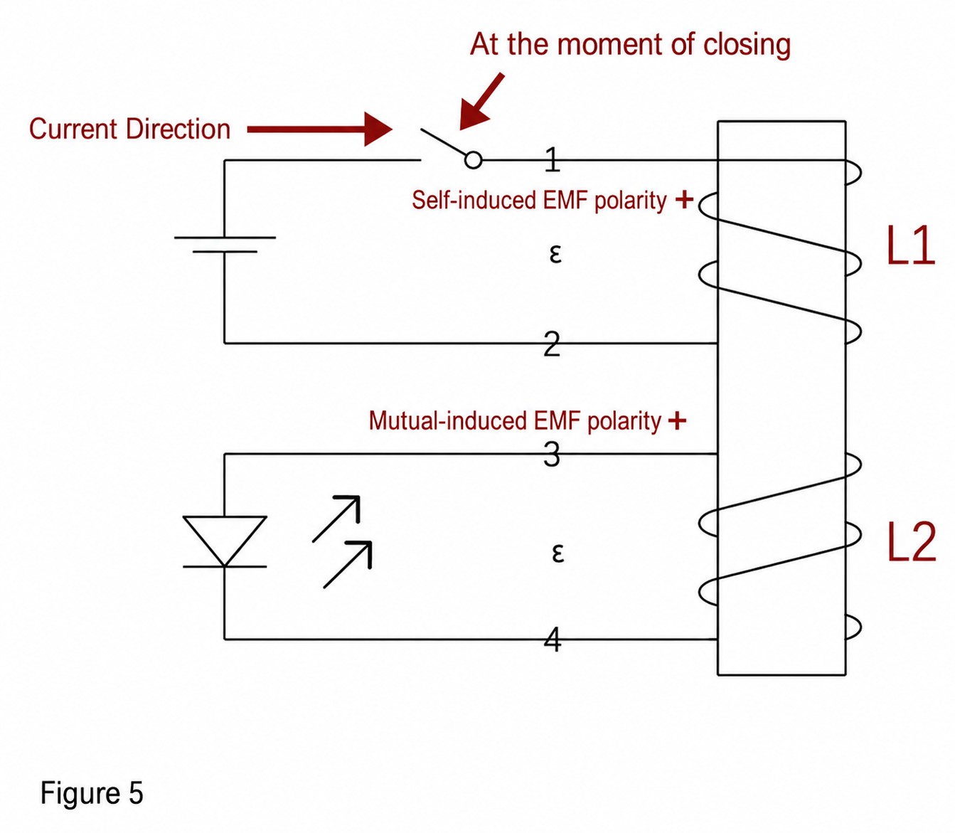
Step 1: Identify the terminals of the two coils and mark them. Step 2: Connect the meter to the two terminals of coil L2 (the relationship between pointer movement and current direction must be known), connect the negative terminal of a dry cell to one terminal of L1, and leave the other terminal disconnected. Step 3: Touch the positive terminal of the dry cell to terminal 1 of L1 and observe the direction of the meter pointer. The method and principle are as follows: at the instant the dry-cell circuit is closed, coil L1 generates a self-induced electromotive force with polarity 1+ and 2−. The corresponding-polarity terminal of L2 must therefore also be positive, and the positive terminal can be determined from the meter pointer's direction of movement. This applies at the instant of connection. At the instant the circuit is opened after connection, the situation is reversed, with polarity 2+ and 1−; identification can continue using the same method. If the internal resistance of the coil is relatively high, another dry cell may be added. If the meter pointer moves only slightly, a lower range may be selected.
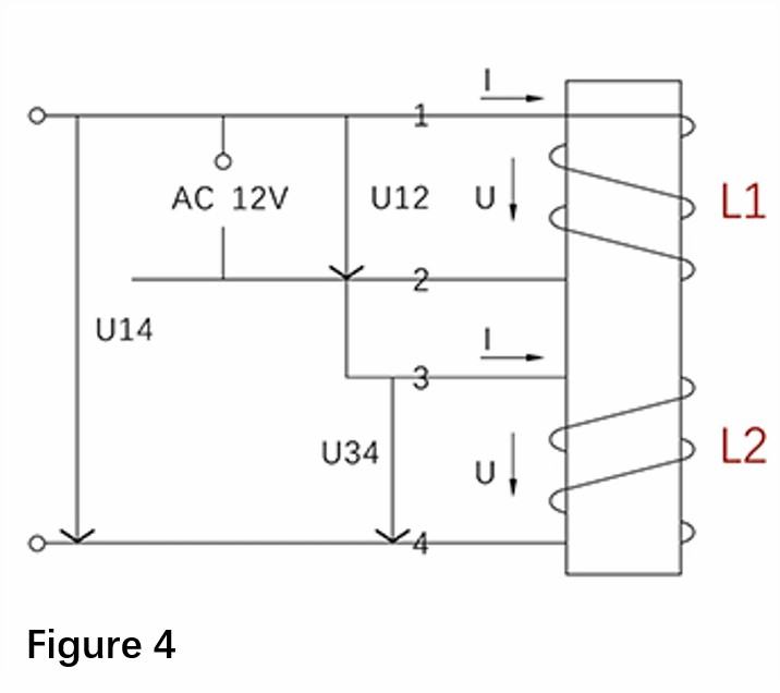
02 AC Voltage Method
Apply a low AC voltage to coil L1 and connect any one lead of L1 to any one lead of L2. Use a multimeter to measure voltages U12, U34, and U14. If U14=U12+U34, terminals 2 and 3 are opposite-polarity terminals; otherwise, they are corresponding-polarity terminals. The principle is that, when the end of one winding is connected to the start of the other, the voltages add; when the starts are connected, the voltages are in phase opposition and the total voltage is their difference.
03 Dry Cell and LED Method
The principle is the same as that of the first method, but this method is simpler. An LED is a diode and illuminates only when its upper terminal is positive and lower terminal is negative. Contact with the dry cell identifies the positive polarity of the self-induced electromotive force; simply observe whether the LED turns on.
|
|
Service Hotline:
021-52212989
18221792228

Service Hotline:
021-52212989
18221792228