Leakage Current and Residual Current
—Mega-Senway Electronic Technology Ltd., Shanghai
—Xu Shouqi, R&D Department
More than a decade ago, when I first entered the low-voltage electrical field, the term ‘leakage-current protector’ puzzled me for a long time. Experienced engineers told me that the device was called a ‘leakage-current protector.’ Yet when I consulted its corresponding Chinese national standard, GB 16917.1-2003 (this edition has since been withdrawn and replaced by an updated edition), it was no longer called a ‘leakage-current protector.’ Instead, it had the more technical name ‘residual current circuit breaker.’ The corresponding English term in International Electrotechnical Commission standard IEC 61009.1-2010 (this edition has likewise since been replaced by an updated edition) is Residual Current operated Circuit Breaker. I later discovered that a similar product is called a Ground-Fault Circuit-Interrupter under the North American standard UL 943, which translates as ‘ground-fault circuit breaker.’
(I would like to add a few observations here. When comparing GB 16917 and IEC 61009, many people believe the Chinese national standard is simply a translation of the IEC standard. I initially understood it that way as well. Years later, however, I learned that because China is a member of the IEC, Chinese standards experts also participate in drafting the English edition of IEC 61009. After the IEC standard is finalized, all IEC member countries directly adopt the English version or translate it into their national languages, and they may also add special requirements reflecting national conditions.)
Many people say that a leakage-current protector is the same as a residual current circuit breaker. In my view, this is both correct and incorrect. It is correct because the products identified by the two names are currently the same. It is incorrect because leakage current and residual current are concepts in different dimensions. Leakage current occurs at the application end when direct or indirect electric shock, or damaged equipment insulation, causes current to flow into ground.
This current is leakage current, a concept similar to the ‘ground fault’ described in North American standards. Residual current, by contrast, does not refer to a particular current; it is the vector sum of the line current and neutral current. We will now examine the distinction between leakage current and residual current in detail.
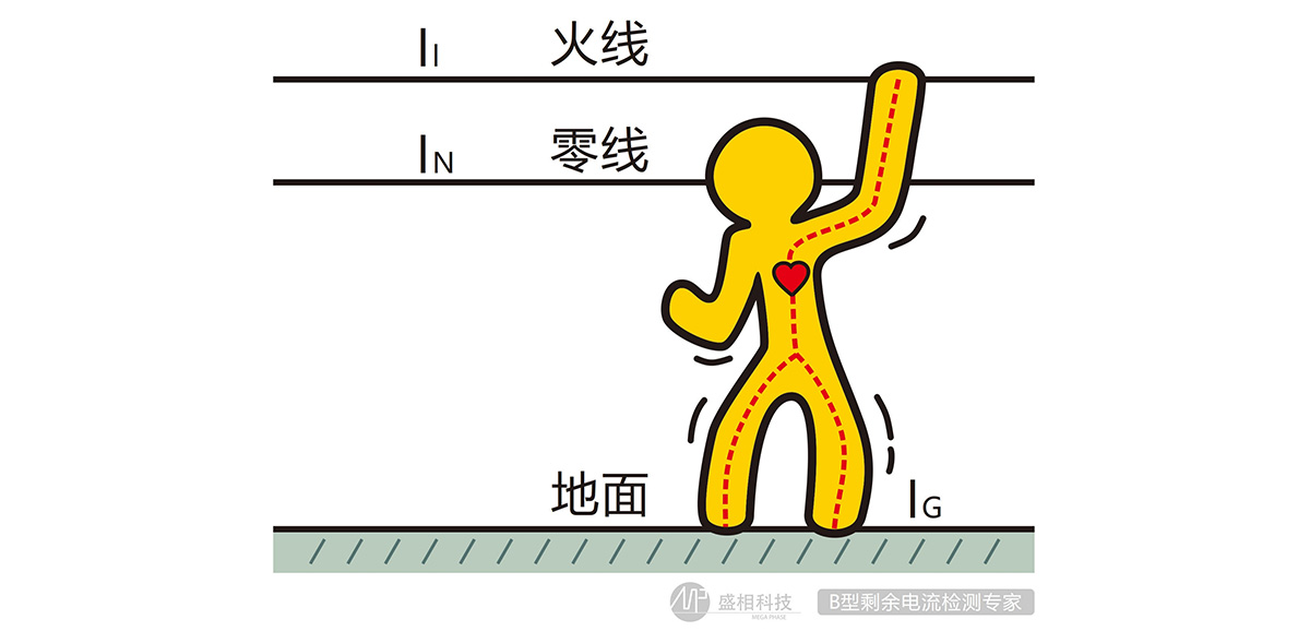
Figure 1: Occurrence of Leakage Current
As shown above, when a person contacts the line conductor, the potential difference between the line conductor and ground causes current to flow from the line conductor through the person and into ground. This current, IG, is leakage current. Residual current is the vector sum of the line current and neutral current, IL+IN. It is important to understand that the direction of AC current changes periodically. The AC frequency in China is 50Hz. In simple terms, for one 10ms interval current flows from line to neutral, and during the next 10ms interval it changes direction and flows from neutral to line. Therefore, when leakage current IG=0, IL and IN are always equal in magnitude and opposite in direction, so the residual current IL+IN=0. When IG≠0, the vector sum of IL and IG+IN is 0, while the vector sum of IL and IN is IL+IN=-IG. In other words, residual current equals -IG.
This description may provide an initial understanding of the difference between leakage current and residual current. Next, we will examine the various forms residual current can take.
Under GB/T 16917.1 (corresponding to IEC 61009.1), residual current has the following forms: AC residual current (AC); residual current with a current lag angle of 0° (also called half-wave residual current) (A0°); residual current with a current lag angle of 90° (A90°); residual current with a current lag angle of 135° (A135°); and residual current with a current lag angle of 0° superimposed on 6mA smooth DC (A0°+6mA).
GB/T 22794 (corresponding to IEC 62423) considers several additional residual current forms: 150Hz AC residual current; 400Hz AC residual current; 1000Hz AC residual current; AC residual current superimposed on DC (AC+DC); pulsating DC residual current generated by a two-phase supplied rectifier circuit (2PDC); pulsating DC residual current generated by a three-phase supplied rectifier circuit (3PDC); smooth DC residual current (SDC); and composite residual current (Type F waveform).
It may be difficult to imagine how a simple leakage event can produce so many forms of residual current. We will now examine the waveform characteristics of these currents and the reasons they occur.
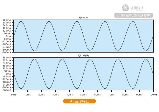
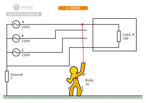
AC residual current (AC): The waveform is AC. The operating principle is straightforward: leakage occurs at an AC voltage point.
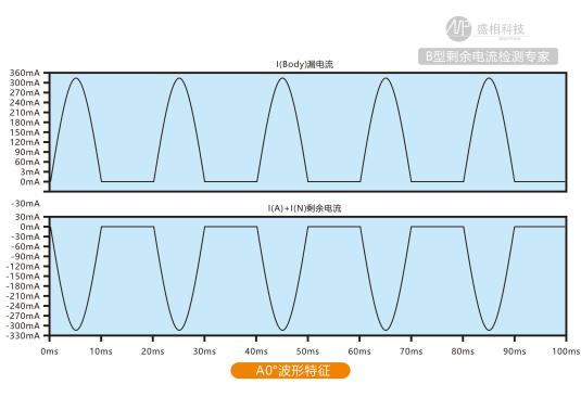
Residual current with a current lag angle of 0° (A0°): The waveform is pulsating DC after half-wave rectification. The corresponding leakage occurs after half-wave or full-wave rectification.
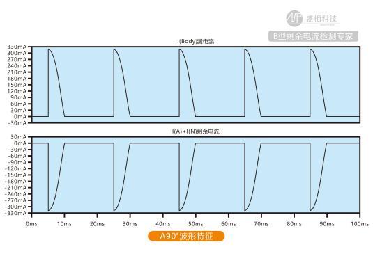
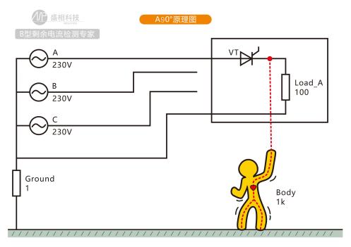
Residual current with a current lag angle of 90° (A90°): The waveform is the right half of the A0° waveform (the 90°~180° portion). The corresponding leakage occurs after half-wave or full-wave rectification, with a rectification lag angle of 90°.
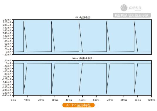
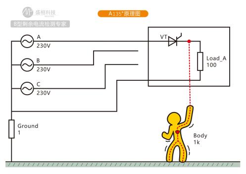
Residual current with a current lag angle of 135° (A135°): The waveform is the right half of the A90° waveform (the 135°~180° portion). The corresponding leakage occurs after half-wave or full-wave rectification, with a rectification lag angle of 135°.
Residual current with a current lag angle of 0° superimposed on 6mA smooth DC (A0°+6mA): The waveform is an A0° waveform shifted upward by 6mA DC. This situation generally occurs when leakage is present across multiple loads: leakage occurs after rectification in one load and after filtering in another.
150Hz AC residual current: The waveform is AC at a frequency of 150Hz. The corresponding leakage occurs at the AC output of a variable-frequency drive.
400Hz AC residual current: The waveform is AC at a frequency of 400Hz. The corresponding leakage occurs at the AC output of a variable-frequency drive.
1000Hz AC residual current: The waveform is AC at a frequency of 1000Hz. The corresponding leakage occurs at the AC output of a variable-frequency drive.
AC residual current superimposed on DC (AC+DC): The waveform is an AC waveform shifted upward by DC. This situation generally occurs when leakage is present across multiple loads: leakage occurs at an AC voltage point in one load and after filtering in another.
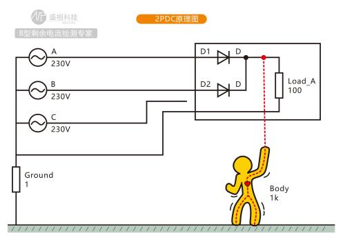
Pulsating DC residual current generated by a two-phase supplied rectifier circuit (2PDC): The waveform has two half-wave rectified peaks in one cycle (20ms) and includes a zero point. The corresponding leakage occurs after rectification in a two-phase power supply.
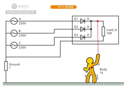
Pulsating DC residual current generated by a three-phase supplied rectifier circuit (3PDC): The waveform has three half-wave rectified peaks in one cycle (20ms) and does not include a zero point. The corresponding leakage occurs after rectification in a three-phase power supply.
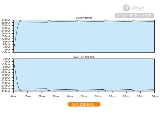
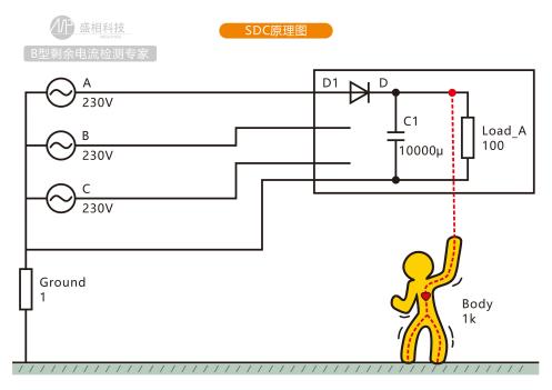
Smooth DC residual current (SDC): The waveform is smooth DC. The corresponding leakage occurs after rectification and filtering. Because a filter capacitor is present, the leakage takes the form of DC.
Composite residual current (Type F waveform): The waveform is a mixture of multiple AC components, as shown in Figure 2.
Component Values at Different Frequencies of the Test Current Used for Calibration (RMS)
Initial Composite Current Value (RMS)
IRated Frequency
I1kHz
IFMotor (10Hz)
IΔ
0.138IΔn
0.138IΔn
0.035IΔn
0.2IΔn
Note 1:IΔnis the rated residual operating current at the RCD’s rated frequency.
Note2:For this test, the 10Hz and 1kHz values represent the output and clock frequency under the most severe conditions, respectively.
Figure 2: Type F Waveform
Based on the description above, we can see that some residual current waveforms do occur in real applications, such as AC, A0°, 2PDC, and 3PDC. When leakage occurs in these applications, the waveform characteristics match the descriptions. Other waveforms simulate certain typical real-world applications, including 150Hz, 400Hz, 1000Hz, A90°, A135°, SDC, and Type F waveforms. When leakage occurs in actual applications, it may not exactly match these descriptions. For example, the frequency may not be 150Hz, 400Hz, or 1000Hz; the rectification lag angle may not be 90° or 135°; the signal after rectification and filtering may not be pure smooth DC; and the waveform characteristics during motor startup may not match Figure 2. We can therefore expect an effectively unlimited variety of leakage-current waveforms, directly related to the load.
Next, we will examine several leakage conditions and waveform characteristics simulated using simulation software.
Table 1: Selected Residual Current Waveforms and Their Operating Principles
|
Waveform Name |
Waveform Characteristics |
Operating Principle |
|
AC |
|
|
|
A0° |
|
|
|
A90° |
|
|
|
A135° |
|
|
|
2PDC |
|
|
|
3PDC |
|
|
|
SDC |
|
|
After discussing so many residual current waveform characteristics, you may wonder whether leakage-current protectors can provide effective protection in every case. Is there a device capable of comprehensively testing their protection characteristics? The answer is yes.
Figure 3 shows equipment that fully covers the residual operating current tests specified in standards including GB/T 16917.1 (IEC 61009.1) and GB/T 22794 (IEC 62423): the eMorse residual current test bench, designed and manufactured by Mega-Senway Electronic Technology Ltd., Shanghai.
The front panel shows that it covers AC, A0°, A90°, A135°, 2PDC, 3PDC, SDC, and Type F composite waveforms, as well as frequencies of 50Hz, 60Hz, 150Hz, 400Hz, 600Hz, 700Hz, 1kHz, 2kHz, and 3kHz. It also supports adjustable superimposed DC. Depending on the residual current level, products are available with maximum outputs of 500mA, 5A, 10A, and 30A.

Figure 3: eMorse Residual Current Test Bench
The test bench also supports automated testing. The accompanying eMorse software automatically controls power-up of the test bench hardware, application of residual current, and full control of fixtures such as automatic reclosers, enabling high-speed, fully automated testing. For Type A and Type B residual current protection products, which involve numerous test items, this approach can improve efficiency by more than 2–3 times compared with conventional fully manual testing. Software-controlled, fully automated testing can also save detailed information from each test, facilitating quality traceability and failure-cause analysis.
Because of its outstanding performance, the test bench has been adopted by numerous low-voltage electrical manufacturers, charging-point manufacturers, and authoritative certification organizations as essential equipment for their R&D, production, and laboratories.
Service Hotline:
021-52212989
18221792228

Service Hotline:
021-52212989
18221792228